AirStack Bitstream
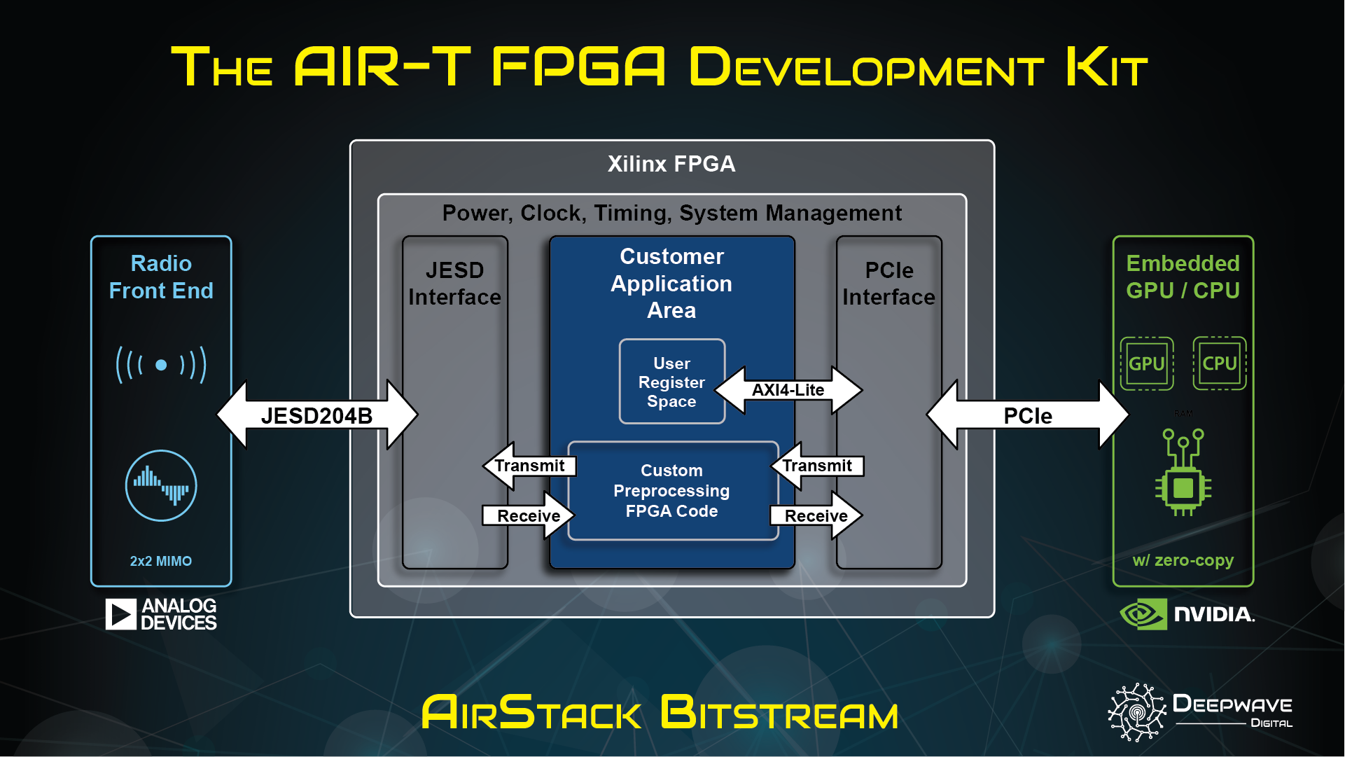
This document is an overview of AirStack Bitstream, which is an environment where custom FPGA designs compatible with AirStack Core software can be created.
License
The license file is included with the download of AirStack Bitstream and may be found on our docs page here.
Prerequisites
- An AIR-T with software the corresponding version of AirStack Core installed for the version of AirStack Bitstream you are using
- A host machine with the following:
- AirStack Bitstream downloaded from the Developer Portal.
- Vivado 2019.2 installed.
- Xilinx JESD204 Core License.
- Confirm
jesd204license visibility in Vivado throughHelp > Manager License... - JESD204 evaluation licenses are compatible with AirStack Bitstream. However, per Xilinx documentation: "the generated bitstream contains circuitry that disables the design after 2 to 8 hours of operation at the typical clock rate for the core. The actual duration of the operational period varies on a core-by-core basis. To start the device working again, you must reload the bitstream (reset or reprogram the device)."
- Confirm
AirStack Bitstream Contents
top_dwd.sv- Top level of the design, instantiates the Deepwave IP core, AXI4-Lite registers, and a default pass through of samples back to the Deepwave IP core.dwd_axil_regs.sv- An example generated AXI4-Lite register space.regrw_test.py- A test script for the AXI4-Lite register space.check_timing.tcl- A supplemental script for Vivado requiring timing to be met by default.dwd_ip- Location of Deepwave IP files.AIR-T_7101- AIR-T 7101 product specific Vivado files.AIR-T_7201- AIR-T 7201 product specific Vivado files.AIR-T_8201- AIR-T 8201 product specific Vivado files.sandbox_diagram.eps- High level block diagram of AirStack Bitstream environment.
Getting Started
- Ensure the prerequisite requirements have been met.
- In the directory where AirStack Bitstream was downloaded extract the
AirStack_Bitstream_<version>.tar.gzarchive:$ tar xvf AirStack_Bitstream_<version>.tar.gz - There are three Vivado projects in the newly created AirStack_Bitstream_
directory. Use Vivado to open the project corresponding to your AIR-T model. AIR-T_7101/dwd.xpr- AIR7101 Model (XC7A75T FPGA)AIR-T_7201/dwd.xpr- AIR7201 Model (XC7A200T FPGA)AIR-T_8201/dwd.xpr- AIR8201 Model (XC7A200T FPGA)
- Open the Vivado project and click the
Generate Bitstreambutton to confirm the full Vivado synthesis and implementation flow functions as expected. The resulting bitstream is compatible with tests mentioned in below sections. (see later sections for expected Vivado build messages).
Loading AirStack Bitstream files into AirStack Core
- In AirStack Core, load the bitstream file into FPGA bitstream flash memory. Note: The
$ load_flash -i 1 top_dwd.bitload_flashutility will not recognize custom Bitstream builds and will report that the contents of your .bit file areUNKNOWN. This is OK. - Shutdown, unplug the power supply to the AIR-T, and plug it back in. The FPGA will only read from the flash memory after a full power cycle.
- Once powered on the AIR-T will load the bitstream from flash and configure the FPGA.
- On the AIR-T run the following to verify the bitstream was loaded successfully: which should return a found AIR-T device with
$ SoapySDRUtil --findDevelopment Buildfirmware and correcthardwarematching your AIR-T product:Found device 0 driver = SoapyAIRT driver_version = X.X.X-X firmware_version = Development Build fpga_driver_version = X.X.X-X hardware = ??01 rf_api_version = X.X.X-X url = https://www.deepwave.ai vendor = Deepwave Digital, Inc.
If any problems are encountered please follow steps for firmware recovery.
JTAG
JTAG can be used for debug (i.e. Chipscope), standard development, and factory firmware recovery/reset. Please see the firmware recovery documentation for how to connect to the AIR-T's JTAG port.
When loading bitstreams into flash memory over JTAG the following information can be used with Vivado Hardware Manager's Tools > Generate Memory Configuration File... dialog:
- Format: MCS
- Memory Part: s25fl256sxxxxxx0-spi-x1_x2_x4
- SPIx4
Testing the Initial Bitstream
Radio Samples Data Path
The AirStack Bitstream FPGA design comes configured for basic radio receive and transmit functionality.
The primary method of communicating to/from the RF hardware (including the FPGA) on the in AirStack Core is via the SoapyAIRT interface. However, SoapyAIRT assumes several things about the configuration of the FPGA. These ssumptions are:
- All data passed to/from the FPGA are complex 16-bit integer time domain samples. Note that SoapyAIRT also supports complex 32-bit floating point samples, but performs an internal conversion.
- Currently, there are two RX and two TX channels. Any missing RF channels are treated as a fatal error by SoapyAIRT and the software will no longer consider the device an AIR-T.
- Currently, samples to/from the RFIC are always transferred at a sample rate of 125 MSPS. See FPGA signal definitions in below sections. No other sample rates are supported without additional interpolation/decimation being added to the FPGA design.
Example - Setting the sample rate to 125 MSPS for receiver channel 0 using SoapyAIRT:
sdr.setSampleRate(SOAPY_SDR_RX, 0, 125e6)
If your FPGA design meets the above assumptions, the SoapyAIRT interface is the simplest path forward.
Please see the following SoapyAIRT examples as a starting point for your application code:
For more complex interactions with the FPGA that break any of SoapyAIRT's assumptions, it is recommended to communicate with the DMA and transceiver device drivers directly. Please contact Deepwave support for code examples and further documentation.
Register Read + Write Test
The AirStack Bitstream FPGA design comes configured with an AXI4-Lite register space. See FPGA AXI signal definitions in below sections.
A test script is included that demonstrates reading and writing those FPGA registers using SoapyAIRT.
-
Run using the following command (no additional arguments required):
$ python3 regrw_test.py -
The test attempts to read and write all the allocated register space. For the subset of the address range currently in use write values are compared to read values to confirm registers are functioning correctly.
Testing allocated FPGA register address space...
Starting at address=0x0
Ending at address=0x1FFFF
Test passed.
SoapySDR Time API Functionality
AirStack Bitstream does not currently support the AirStack Core Time API for precise timing of transmit and receive samples. The time API functionality in AirStack COre expects to see an FPGA configured with the standard AirStack Core firmware. Custom designs produced from AirStack Bitstream only support basic receive and transmit SoapySDR functionality as described above.
Signal Definitions
The names referenced here are from top_dwd.sv.
Clock and Reset:
dwd_axi_clk- 125MHz clock for the AXI4-Lite interface provided by the Deepwave Digital IP core.dwd_axi_aresetn- AXI4-Lite interface reset, active low, asynchronous.dwd_axis_clk- 125MHz clock for all AXI4-Stream interfaces provided by the Deepwave Digital IP core.dwd_rx_axis_rst[1:0]- AXI4-Stream receive datapath resets, per channel, active high, synchronous.dwd_tx_axis_rst[1:0]- AXI4-Stream transmit datapath resets, per channel, active high, synchronous.
AXI4-Lite Interface
dwd_m_axil_*- AXI4-Lite bus for provided register space.dwd_axil_regs- An example generated AXI4-Lite register space module.
The total address space available on this AXI4-Lite bus is 128Kb (17b addresses from 0x00000000 - 0x0001FFFF). The example register space instantiates 32 four byte (32b) registers, occupying addresses 0x00000000 - 0x0000007C.
Please refer to the AXI Reference Guide for more information.
AXI4-Stream Interfaces
Serial 16b IQ samples pairs are in decoded from the 32b AXI4-Stream word as follows:
I = tdata[15:0];
Q = tdata[31:16];
All interfaces are in AXI4-Stream format with some limitations, as described below. Please refer to the AXI reference guide.
AXI4-Stream Limitations
tuserandtstrbsignals are not present nor supported.tkeepsignals are present but not supported by the software driver. It is required that all 32 bits of the 32btdatasignal are set and valid for each beat.- Optional
tdestandtidsignals are not present. These signals are used for multiplexing multiple logical streams over a single bus interface. Each of our AXI4-Stream interfaces represents a single logical stream, mapped one-to-one to a stream presented to software by the DMA controller.
Receive
dwd_rx*_m_axis_*- Output stream of samples received from the radio. There is no buffering behind this interface. Constant flow control ready is assumed, deasserting dwd_rx0|1_m_axis_tready drops dwd_rx0|1_m_axis_tdata samples.dwd_rx*_s_axis_*- Input stream of samples for DMA read. Flow control dwd_rx0|1_s_axis_tready is asserted as DMA reads occur.
Transmit
dwd_tx*_m_axis_*- Output stream of samples from DMA write.Stream dwd_tx0|1_m_axis_tvalidis asserted as DMA writes occur.dwd_tx*_s_axis_*- Input stream of samples transmitted to the radio. A constant stream of samples is expected during transmission. Whendwd_tx0|1_s_axis_tvalidis deasserted and does not provide new samples for transmit recentdwd_tx0|1_s_axis_datasamples continue to be transmitted untildwd_tx0|1_s_axis_tvalidis asserted again (or the radio is turned off).
Expected Vivado Build Messages
Upon successful bitstream creation Vivado will report many messages. Expected messages have been documented in spreadsheets exported by Vivado.
-
AIR7101 Model (XC7A75T FPGA) Project:
- Synthesis: 41 Critical Warnings, 350 warnings. Implementation: 188 Warnings.
AIR-T_7101/expected_vivado_messages.xlsx
-
AIR7201 Model (XC7A200T FPGA) Project:
- Synthesis: 41 Critical Warnings, 350 warnings. Implementation: 188 Warnings.
AIR-T_7201/expected_vivado_messages.xlsx
-
AIR8201 Model (XC7A200T FPGA) Project:
- Synthesis: 46 Critical Warnings, 351 warnings. Implementation: 188 Warnings.
AIR-T_8201/expected_vivado_messages.xlsx